Cost Optimization Strategies in CNC Machining based on Design
CNC machining stands for precision, quality and reliability like hardly any other manufacturing process. These characteristics make CNC-machined components ideal for applications where tight tolerances and functionality are important. However, CNC-machined components tend to be more expensive than components of comparable size produced by other manufacturing processes. In this article, we want to give you tips on how to design and procure CNC components cost-effectively, so that small companies, research institutions and start-ups can also gain access to high level CNC technology at attractive costs.
CNC machining time can be considered the most important cost-generating parameter, exceeding material costs, initial capital costs, and also custom finishing costs incurred as part of surface or heat treatments . Therefore, the highest cost optimization in the CNC manufacturing process is achieved by reducing machining time. The optimal method for reducing machining time can be achieved by implementing a viable design process, also known as "design for manufacturing." Key strategies for optimizing CNC manufacturing costs include both improvements to the machined part, machine tool geometry, and drill sizes, as well as simplifying the manufacturing of complex geometric components. However, later in the article we will see that great savings effect can be achieved through an efficient digital purchasing strategy as well.
CNC Machining Principles
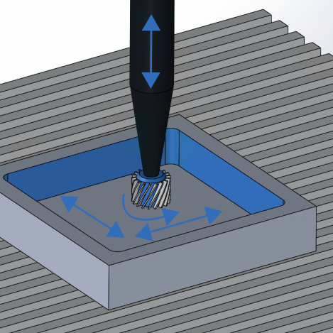
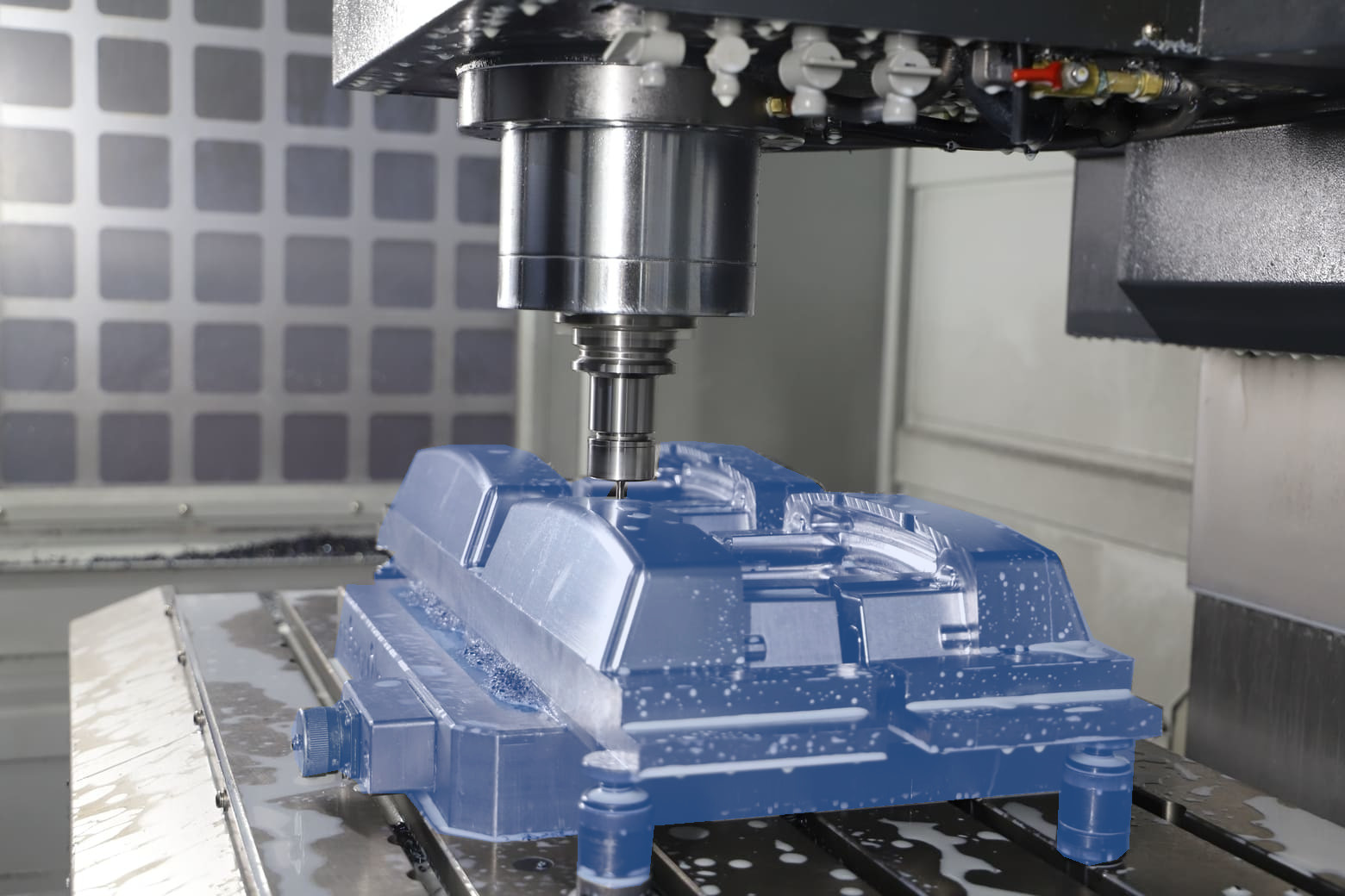
In milling or turning, rotating cutting tools are used to remove material from a block. In this process, the target geometry is created by removing material layer by layer. The engagement of the cutting tools with the base material produces chips. Both the workpiece and the milling tool can be moved in different directions. Simple milling machines have three axes of motion in which the milling tool is moved linearly along the spatial coordinates in the x, y and z directions. In 5-axis milling machines, the clamping table with the component and/or the tool is tilted around two axes.
As the complexity of the component increases, more axes are required to reach all points of the surface with the milling tool. Therefore, to save costs in manufacturing, the part should be designed to be only as complex as necessary, and unnecessary features should be eliminated. Here are some tips for the design.
Rounding CNC Machine Tool’s Internal Corners
An optimal CNC workpiece machinability must allow for better material removal, which can be accomplished by increasing the workpiece's inside corner radius to allow the tool to make fewer repetitive passes throughout the milling or machining process. A geometry with a tighter inside radius be machined with smaller machine tools at lower speeds, reducing the risk of tool breakage or deflection at the expense of longer machining times. However, a viable design set for a machinable part includes an inside radius with a length- to-diameter ratio of 3:1.
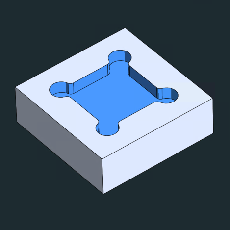
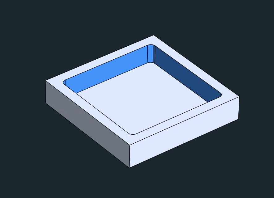
In summary, cost minimization can be achieved by rounding the inner geometric corners:
1. Adding a radius of at least 1/3 of the cavity depth
2. Using a similar radius for all inner edges to avoid tool changes
3. At the bottom of the cavity, a small radius shall be used, either 0.5 mm or 1.0 mm or no radius at all
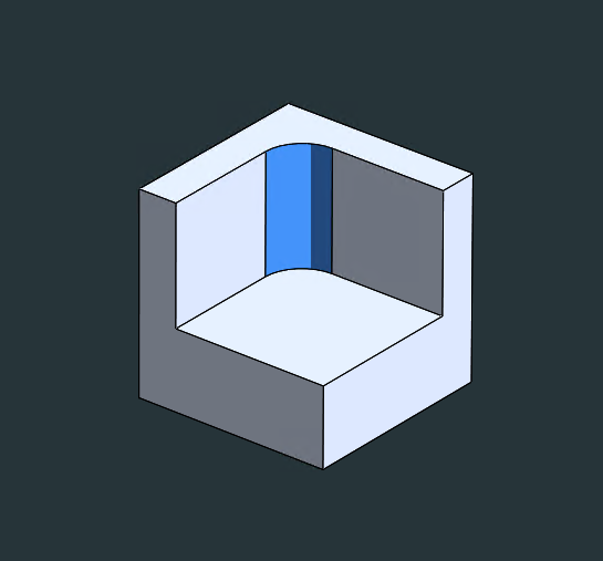
A geometric requirement for sharper inner edges, especially when a rectangular shape is to fit into a cavity, is achieved by using a geometric shape like that in the shown Figure with undercuts rather than reducing the inner edge radius of the geometry.
Limiting Depth Parameter of Cavities and Deep Pockets
Machining deeper geometric cavities causes high costs due to the larger volume of material removal. Due to the limited cutting length of CNC tools, the optimum cutting performance for cavities is at a depth twice or three times their diameter. For example, a milling tool with a diameter of 12.0 mm can easily cut cavities up to a maximum depth of 25.0 mm. Deeper cavities can also be cut (up to a maximum of four times the diameter of the milling tool or higher), but at a higher cost because special tooling or low passing speeds are required.
Therefore, it is optimal to reduce the cavity depth to four times the length of the cavity, which is then the largest XY plane dimension. Gradual lowering of the end mill with smaller fragments or other methods such as wire eroding and broaching can solve problems with deep pockets, but are associated with higher costs.
Limiting the Length of Threads
The length of the threads should not exceed 1.5 times the thread hole diameter from a structural point of view, and lengths exceeding the specified parameter do not contribute to the overall strength, but rather increase the cost of CNC machining of the parts. However, blind tapped holes must be at least half the diameter of the unthreaded length at the bottom of the blind hole.
Using Standard Hole Sizes and Optimizing Hole Design
Standard size drills can be used for accurate hole machining. Non-standard sizes increase machining costs due to longer machining time. It is less expensive to machine through holes rather than blind holes, and it is optimal to include through holes in a geometry during the design process. The hole depth should be limited to four times its diameter, as deeper holes (depth greater than ten times the diameter) require longer machining times, making the overall process very expensive. It is recommended to design holes with a diameter increment of 0.1 mm for diameters up to 10.0 mm, while diameters above 10.0 mm can be considered with a 0.5 mm step.
Parametric optimization of tapped holes during machining
The depth of the hole and the size of the tap are the most important parameters considered when optimizing the geometry of the tapped holes of the components to be machined. Increasing the thread length of a tapped hole to the nominal range, which is no more than three times the hole diameter (thread length = 3x hole diameter) or shorter, is optimal, rather than going deeper, which may lead to tool fracture (breakage) and will lengthen the tapping process. Standardized tap sizes can significantly reduce tapping costs due to the easy availability of common tools. For example, 4-40 mm size taps are commonly available on the market rather than much smaller or bigger size taps. It is recommended that smaller taps not be used because those require manual tapping, which increases tapping time and increases the risk of tap breakage.
Specifying Necessary Tolerances on Machinable Components
One of the primary reasons for high costs in machining is the presence of tighter tolerances, which increases the complexity and difficulty of the process. Therefore, it is important to establish geometric tolerances on machinable parts only when necessary. In cases where specific tolerances are not defined on engineering drawings or part/component layouts, a standard tolerance level shall be maintained, which is suitable for almost all non-critical geometric features.
Machining costs can be further regulated by defining a single reference point as the reference parameter for all geometric dimensions with tolerances. Geometric dimensioning and tolerancing (GD & T) in engineering drawings includes geometric features such as flatness, straightness, circularity and positional accuracy, which should be used with care as they are dominant cost drivers.
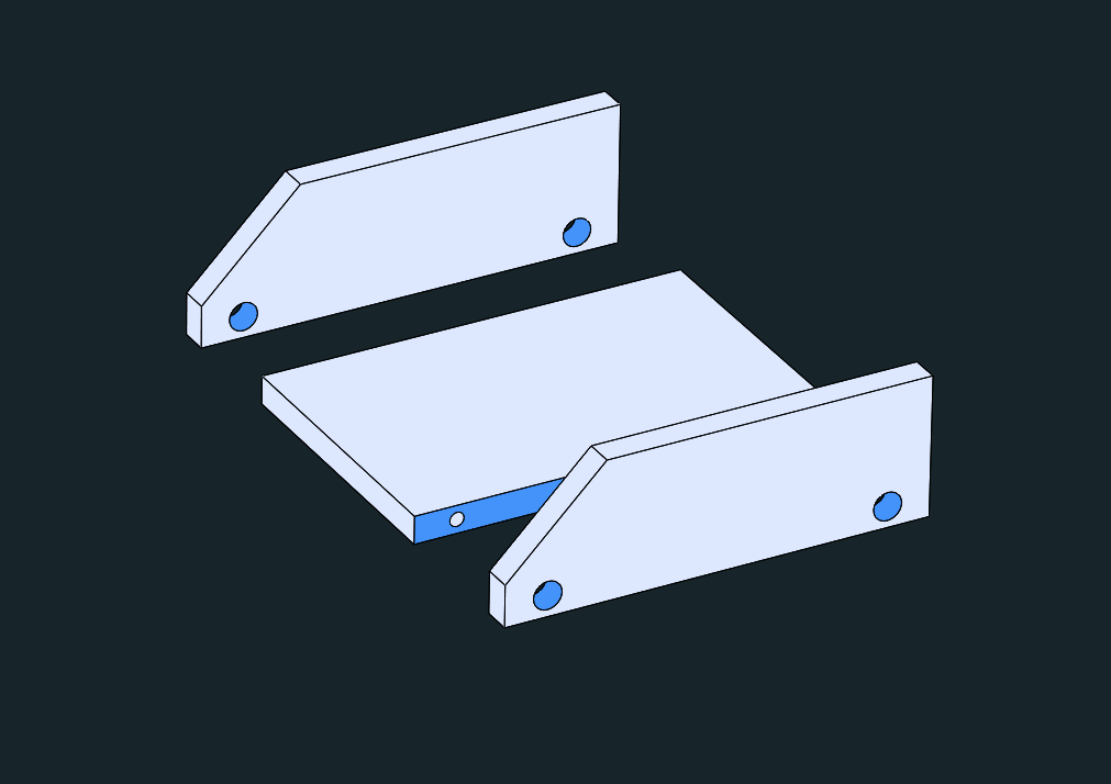
Minimizing the Number of Machining Setups and Configurations
It is ideal to design geometric parts that can be machined with as few operations as possible in a single machining setup. For example, a part with blind (hidden) holes on both sides of the geometry requires machining in two setups because it must be rotated to make both sides of the part accessible. Rotating or repositioning the part increases machining costs because it requires manual labor or additional machine axis.
In addition, components with complex geometric features require machining by multi-axis CNC system, which drives up manufacturing costs. Splitting complex components into multiple geometric parts that can be machined by a single CNC device and then bolted or welded together is therefore highly desirable, especially for geometries with deeper pockets.
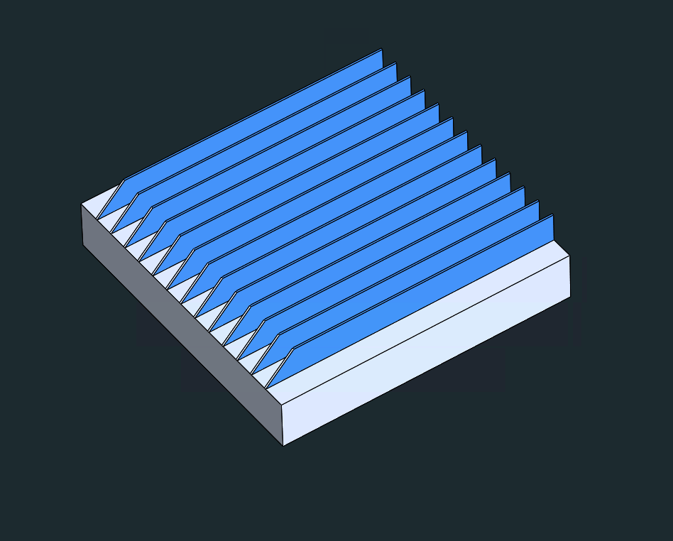
Avoid smaller Features Having higher Aspect Ratios
Smaller geometric features with a larger height-to-width (H:W) ratio are more prone to vibration during the machining process, which reduces overall accuracy. Adding stiffening supports to such smaller geometric features or integrating them into other wall structures increases their overall structural stability and stiffness.
Lower CNC Machining costs can be attained by maintaining a maximum Height : Thickness (H:T) ratio of 5:1. Larger H:T ratios result in unsatisfactory surface finishing, and chatter marks may appear. Moreover, machining process of thin wall part geometries might require complex setups and fixtures further increasing fabrication costs. Designing parts with short and thick walls (reducing height) enhances rigidity of geometric structure which allows faster machining thus lowering fabrication and milling costs.
The addition of geometric entities as supporting elements including jogs and curved walls to thin wall structures can help reinforce part geometry and enhance structural rigidity allowing for further wall thinning (reducing thin wall thickness to a greater extent). Height to Length (H:L) ratios of 25:1 can be maintained in specific part geometries including short wall or rib elements supported at either end without much effect on machining costs.
Prevent Thin Walls on your CNC Milled Parts
During CNC machining, workpieces with thin walls (edges with small thickness) may deform due to vibrations. Such geometric deformations make it impossible to maintain the specified tolerances and increase machining costs. The recommendation to maintain a minimum width of 1/32 inch or 1 mm for thin walls can help regulate machining costs by avoiding the risk of structural deformation. However, when maintaining a thickness less than the recommended width is essential for very thin-walled geometries, EDM processes can be used, increasing the cost of the part.
The engineering design of CNC machinable components is optimized for light weight, reduced thickness, and durable performance. To achieve such integral designs, thin walls are now being incorporated into component geometry, especially in aerospace and avionics where lightweight and durable parts are of paramount importance. The use of thin walls is therefore critical for lightweight applications, but there are limitations in manufacturing in terms of design integrity and stability of the part, especially when the cost factor is taken into account. Manufacturing costs and thin wall thickness parameters can change
Considering Blank Size of Geometry
The overall "size"dimensions of the blank or base material affect the machining cost. The recommended blank size is at least 3.0 mm larger than the finished part dimensions. To ensure accurate machining, material is removed from the cumulative edges of the machinable part.
For example, for a part with dimensions 30mm×30mm×30mm, a larger blank is used, which in this case is cut from a sheet with dimensions 35mm×35mm×35mm. For parts with dimensions 27mm×27mm×27mm, a sheet with dimensions 30mm×30mm×30mm is used as a blank for machining, resulting in a large material saving compared to the first example. The technique of keeping the final dimensions of the part 3.0mm smaller than the available standard blank dimensions allows significant material savings and better machinability of the parts.
Removal of Textual and Lettering Features from Machinable Parts
Adding text features to the surface of workpiece geometries increases machining costs due to additional machining steps, thus increasing overall process time. Adding text features to the surface of CNC machined parts can alternatively be done by screen printing, painting or laser engraving
Clarity in CNC machining of lettered part surfaces can be achieved by using at least 20-point Serif or Arial fonts.
Regulating Multi-Surface Finishing of Machinable Components
It is strongly recommended to use a uniform surface treatment technique to regulate both the costs and the process steps involved. The application of anodizing or chemical film surface treatments to the surfaces of machined components involves a mixture of both surface treatment processes. This is also the case when the surface of a single part requires a smooth surface treatment in a certain area and a bead blasting treatment in the remaining area.
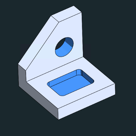
Simplify Complex Geometric Parts into Machinable Components
In certain applications, complex geometries can be simplified into simpler and smaller machinable components, in which these components have been designed as separate integral components and integrated as a single complex assembly by either bolting or other joining processes. The simplification strategy can be applied to parts with deep pockets or cavities that require hours of extensive machining to remove material after the component is manufactured, which can be expensive and tedious. Simplification strategies can facilitate machinability and reduce associated costs.
Integration of Chamfers and Fillets to CNC Machined Part Geometries
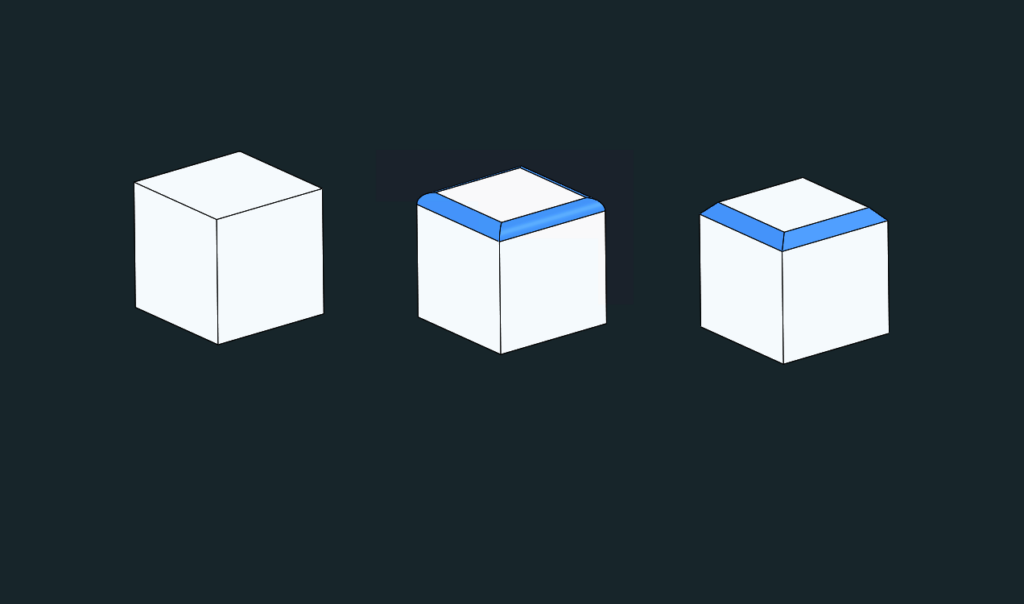
Chamfers and fillets are geometric features added to machinable parts that increase both machining time and cost. Fillets are rounded corners of a machinable part or component that are added to reduce the stress level at the corners of the geometry. Chamfers, on the other hand, are added to angled or sloped component edges, especially when the orientation is 45⁰ or 60⁰. Both fillets and chamfers help smooth sharp edges and increase the load capacity of the machinable component. Chamfers have a lower load capacity because stress is concentrated at the edges, while fillets spread stress over a larger area, resulting in better stress distribution.
Both chamfering and fileting improve the esthetics of a part. Objects that are handled by humans are unsafe if the corners remain sharp, and both chamfering and rounding may be necessary. In either case, the function of the product should not be compromised by the addition of rounded edges, and whether reinforcement is needed for long-term durability are all questions that help determine the right corner type for any part geometry.
Reducing Costs of CNC-Machined Parts through the Use of Purchasing Platforms for Milled and Turned Parts
As in any B2B purchasing process, the object of purchase determines the price on the one hand, but also the general competitive situation and access to suppliers on the other. The above-mentioned measures for optimizing component designs and hereby costs create the basis for producing easily manufacturable components with little coordination effort.
With optimized components, many offers can be obtained and expensive single-sourcing situations can be avoided. However, this makes purchasing processes complicated, time-consuming and difficult to track, as various offers have to be analyzed and compared. Attention must also be paid to possible taxes, import duties, shipping and delivery conditions. Uncertainties about the expected quality also make strategic sourcing of suitable partners more difficult.
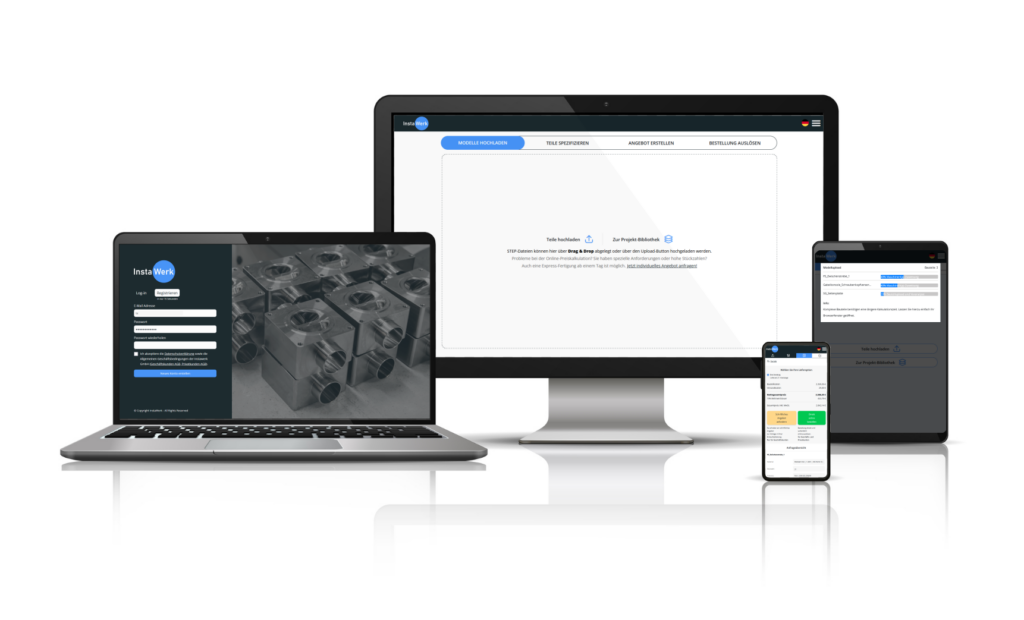
InstaWerk as a procurement platform offers the advantage of a distributed purchasing process with the simplicity of a digital solution. The milled parts to be produced can simply be uploaded as a CAD file into the online calculator to get an instant quotation. A variety of materials, tolerances and surface requirements are available to choose from, as well as all common finishing treatments.
Behind the scenes, InstaWerk operates a network of exclusive CNC manufacturers with access to several thousand CNC milling machines. By bundling orders, InstaWerk is able to realize excellent terms that would not be possible if purchased individually. Due to the exclusive and confidentiality-oriented network, non-disclosure and quality always come first.
And best of all: the process is simple, free of charge and can be tried out immediately and without any obligation in our online calculator for turned and milled parts. Start ordering with InstaWerk now and get your parts done right.
Why choose InstaWerk?